Showing posts with label Engineering articles. Show all posts

Wednesday, August 15, 2018

CHARACTERISTICS OF AN IDEAL WORKING FLUID

    CHARACTERISTICS OF AN IDEAL WORKING FLUID


We all know any thermodynamic power cycle depends on some working fluid for the transfer of heat from source to the point where it is converted to some useful work. Picking a working fluid for any vapour power cycle is not a random decision, since in case of any malfunction caused by it can lead to danger to human life and can cause huge operation and maintenance cost. While choosing a working fluid for a vapour power cycle one should keep following points in his mind. These points suggests the properties of ideal working fluid.

1.  The working fluid should have high critical point temperature so a working fluid with high critical point temperature can provide the opportunity of using considerably lower pressure to reach the higher temperature.
2.  The saturation pressure at the temperature of heat rejection should be above atmospheric pressure.
3.  The working fluid should have lower pressure at higher temperature.
4.  The specific heat of working fluid should be less so that little heat transfer is required to reach the boiling point.
5.  The freezing point of the liquid should be below room temperature such that they don’t get solidified in the pipelines.
6.  The saturated vapour line of T-S diagram should have steep enough such that the turbine expansion line is almost parallel to it and turbine exhaust point doesn’t become very wet.
7.  The liquid should be chemically stable and should not contaminate the material of construction at any temperature.
8.  The fluid should be non-toxic, non-corrosive, not excessively viscous and it should low in cost.


Sunday, August 12, 2018

REGENERATIVE CYCLE EXPLANATION

                       REGENERATIVE CYCLE

This section will introduce one such cycle - the ideal regenerative Rankine cycle, which increases the fluid average temperature during the heat addition process. To save fuel, efforts are constantly made to improve the efficiency of the cycle on which steam power plants operate. The general idea is to increase the fluid average temperature during heat addition and decrease the fluid temperature during heat rejection.
Increasing the temperature of the feedwater (water leaving the pump and entering the boiler) can be considered. This is accomplished by extracting stream from the turbine to heat the feedwater. This process is called regeneration and the heat exchanger where heat is transferred from steam to feedwater is called a regenerator, or a feedwater heater. There are actually two main types of feedwater heaters. If the steam mixes with the compressed water from the pump, it is an open feedwater heater. If the steam does not mix with the compressed water from the pump, it is a closed feedwater heater.
schematic of a power plant running an ideal regenerative rankine cycle with feed water heater.
                               
T-S diagram of ideal regenerative rankine cycle with feed water heater
                                                 
 In an ideal condition, the water leaves the heater as a saturated liquid at the heater pressure. The schematic of a steam power plant with one open feedwater heater is shown on the left. In an ideal regenerative Rankine cycle with an open feedwater heater, steam from the boiler (state 1) expands in the turbine to an intermediate pressure (state 2). At this state, some of the steam is extracted and sent to the feedwater heater, while the remaining steam in the turbine continues to expand to the condenser pressure (state 3). Saturated water from the condenser (state 4) is pumped to the feedwater pressure and send to the feedwater heater (state 5). At the feedwater heater, the compressed water is mixed with the steam extracted from the turbine (state 2) and exits the feedwater heater as saturated water at the heater pressure (state 6). Then the saturated water is pumped to the boiler pressure by a second pump (state 7).The water is heated to a higher temperature in the boiler (state 1) and the cycle repeats again.
Note that the mass flow rate at each component is different. If 1 kg steam enters the turbine, m kg is extracted to the feedwater heater and (1-m) kg continues to expand to the condenser pressure. So if the mass flow rate at the boiler is M, then the mass flow rate from other components are:
      Condenser: M (1-m)
      Pump 1: M (1-m)
      Feedwater Heater: Mm +M(1-m) = M
      Pump 2 : M

For convenience, heat and work interactions for regenerative Rankine cycle is expressed per unit mass of steam flowing through the boiler. They are:
      Heat Input: Q IN = h1 – h7 
      Heat Output: Q
OUT = (1 - m)(h4 – h3)
      Work Output: W
TURBINE OUT= (h1 – h2) + (1 - m)(h2 – h3)
      Work input: W
PUMP IN  = (1 - m)(h5 – h4) + (h7 – h6)
Open feedwater heaters are simple and inexpensive, and can also bring the feedwater to saturated state. However, each feedwater needs a separate pump which adds to the cost.

Monday, August 6, 2018

What are the different types of fluid flow

     What are the different types of  fluid flow

   a)  Steady flow: It is defined as that type of flow in which the fluid characteristic like velocity, pressure, density do not change with time.
   b)  Unsteady flow: It is defined as that type of flow in which the fluid characteristic like velocity, pressure, density etc at a point changes with time.
   c)   Uniform flow: The velocity of flow of a fluid, if constant at any section in the path of fluid flow, then it is called uniform flow. Example – Liquid through a pipe of  uniform cross section.
   d)  Non-uniform flow: The velocity of a fluid, if not constant at any section in the path of the fluid flow, then it is called non-uniform flow. Example: Liquid flows through a pipeline of variable diameter.
   e)  Rotational flow: Rotational flow is that type of flow in which fluid particles while flowing along stream line, also rotates about their own axis.
    f)    Irrotational flow: Irrotational flow is a flow in which each element of the moving fluid undergoes no net rotation with respect to a chosen coordinate axes from one instant to other. A well-known example of irrotational motion is that of the carriages of the Ferris wheel (giant wheel). In a Ferris wheel although each carriage follows a circular path as the wheel revolves, it does not rotate with respect to the earth, as a result the passengers remain upright and continue to face the same direction.
    g)   Laminar flow: It is defined as that type of flow, in which fluid particles, moves in a well defined path or stream line. All the stream lines are straight and parallel. The path of one particle dose not cross the path of any other particle.
    h) Turbulent flow: Turbulent flow is a type of fluid (gas or liquid) flow in which the fluid undergoes irregular fluctuations, or mixing, in contrast to laminar flow, in which the fluid moves in smooth paths or layers. In turbulent flow the speed of the fluid at a point is continuously undergoing changes in both magnitude and direction. The flow of wind and rivers is generally turbulent in this sense, even if the currents are gentle. The air or water swirls and eddies while its overall bulk moves along a specific direction.


Sunday, August 5, 2018

HOW DOES RECIPROCATING PUMP WORKS

          HOW DOES RECIPROCATING PUMP WORKS


In this article we will discuss about working of reciprocating pump so let’s start it.

When the crank starts rotating, the piston moves to and fro in cylinder. When crank is at, the piston is at the extreme left position in the cylinder. As the crank is rotating from A to C (i.e., from 00 to 1800 ) the piston is moving towards right in the cylinder. The movement of the piston towards right create partial vacuum in the cylinder. But on the surface of the liquid in the sump, atmospheric pressure is acting, which is more than the pressure inside the cylinder. Thus the liquid is forced in the suction pipe from sump. The pressure of the liquid opens the suction valve and enters the cylinder.

sketch of a reciprocating pump
                         

When the crank is rotating from C to A (1800  to 3600 ) the piston its extreme right position starts moving towards left in the cylinder. The movement of piston towards left increases the pressure of the liquid inside the cylinder more than the atmospheric pressure. Hence suction valve closes and raised to the required height.


Friday, August 3, 2018

WHAT IS LBM PROCESS?

              WHAT IS LBM PROCESS?

Leaser Beam Machining (LBM): The full form of the term “Laser” is light amplification by simulated emission radiation. The basic elements of LBM are –

                                  I.          Laser rod tube (which is made of glass coated with reflecting material).
                                II.          A flash lamp (which is source of energy).
                             III.          A pair of mirrors (one at each end of the tube).
                             IV.          An amplifying source.
                               V.          A source of power supply (A.C or D.C.)
                             VI.          A cooling system
                          VII.          A lens(which is the focusing source)


When the system is connected to the power line, light energy is thrown on to the ruby rod. This excites the atoms of the inside media, which absorbs the radiation of incoming light energy. This produces to and from mirror does not reflect the total light back and a part of it goes out in the form of coherent stream of monochromatic light. This highly amplified stream of light is focused through a lens which converges the beam light to the required point on the work piece. This high intensity laser beam melts the work piece material and even vaporizes it.

Application of LBM process: LBM not a mass material removal process but it is possible to use this process in mass micro machining production.

                       I.          Trimming of carbon resistors
                    II.          Drilling small holes in hard materials like tungsten and ceramics
                 III.          Shaping complex profiles on thin and hard materials
                 IV.          Cutting or engraving patterns on thin layers.
                    V.          Dynamic balancing of precision rotating part such as of watches.
                 VI.          Cutting of sheet metal and plastic parts.

Advantage of LBM:

                   I.          There is no direct contact between the tool and the work piece. Hence tool wear is out of question.
                II.          Any material can be easily machined irrespective of its structure, mechanical and physical properties.
             III.          The method can be effectively used for welding of dissimilar metals.
             IV.          Heat affected zone around the machined surface is small.
                V.          Very small holes and cuts can be made with high degree of accuracy.


Thursday, August 2, 2018

WORKING PRINCIPLE OF CENTRIFUGAL PUMP


WORKING PRINCIPLE OF CENTRIFUGAL PUMP

A centrifugal pump pressure head is created by centrifugal action of liquid. This is imparted to the liquid by the rotating impeller.
Before starting the pump, air is driven out by a method called priming. After removing air, the pump is started to rotate the impeller. This imparts centrifugal head to the liquid and liquid leaves the vanes of the impeller from the outer circumference with high velocity and pressure and enters the casing. The design of the casing is such that during the flow of liquid through the casing, it’s velocity head is converted into pressure head. Thus the outlet of the casing, the pressure head of the liquid becomes very high. When the liquid leaves the impeller, vacuum is created it’s centre. As a result, the liquid which is under atmospheric pressure in the pump, sucks through the suction pipe to the centre of the impeller and the operation is then repeated.


A centrifugal pump is one of the simplest pieces of equipment in any process plant. It's purpose is to convert energy of a prime mover(a electric motor or turbine) first into velocity or kinetic energy and then into pressure energy of a fluid that is being pumped. The energy changes occur by virtue of two main parts of the pump, the impeller and the volute of diffuser. The impeller is the rotating part that converts driver energy into the kinetic energy. The volute or diffuser is the stationary part that convert the kinetic energy into pressure energy. We know all of the forms of energy involved in a liquid flow system are expressed in terms of feet of liquid i.e., head generation of centrifugal force, the process liquid enter the suction nozzle and then into eye (centre) of a revolving device known as an impeller. When the impeller rotates, it spins the liquid sitting in the cavities between the vanes outward and provides centrifugal acceleration.
As liquid leaves the eye of the impeller a low-pressure area is created causing more liquid to flow toward the inlet because the impeller blades are curved, the fluid is paused in a tangential and radial direction by the centrifugal force. This force acting inside the pump is the same one that keep water inside a bucket that is rotating at the end of string.


Tuesday, July 31, 2018

WORKING PRINCIPLE OF A FOUR-STROKE CYCLE DIESEL ENGINE (ALONG WITH IT’S P-V AND VALVE TIMING DIAGRAM)


 WORKING PRINCIPLE OF A FOUR-STROKE CYCLE DIESEL ENGINE (ALONG WITH IT’S P-V AND VALVE TIMING DIAGRAM)
  

Four-stroke diesel engine: A four stroke diesel engine contains a fuel injector fuel pump, cylinder, cylinder head, inlet and exhaust valves, piston attached with piston range, connecting rods, crank shaft, corns, camshaft, etc. One cycle of a four stroke diesel engine is completed in four strokes of the piston or two revolution of the crank-shaft.

WORKING OF ENGINE:

1. Suction Stroke: The inlet(suction) valve opens, the exhaust valve or outlet valve remain close, only air is drawn into the cylinder as the piston moves from the  top dead center to the bottom dead center. This stroke ends as the piston approaches the bottom dead center (B.D.C).

2. Compression stroke: As the piston moves from bottom dead center to top dead center, the inlet valve closes, exhaust valve remains closed. The air trapped into the cylinder is compressed in the cylinder till the piston approaches the top dead center. The air temperature reaches about 800°C by compression. At the end of the compression stroke, the fuel is injected at very high pressure into the compressed hot air. The temperature of compressed hot air is sufficient to ignite the injected fuel. Thus, ignition keeps place into the cylinder.


3. Expansion Stroke: During expansion stroke, both valve remain closed. The piston at top dead center is pushed by expansion of burning gases. Actual work is obtained during this stroke due to the force obtained by high pressure burning gases. Therefore, this stroke is called power stroke or working stroke.

4. Exhaust Stroke: During this stroke the piston moves from the bottom dead center to the top dead center, exhaust valve opens and the inlet valve remain closed. Burnt gases of the previous stroke are expelled out from the cylinder of upward movement of the piston.


Sunday, July 29, 2018

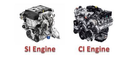
Difference Between SI Engine and CI Engine


Difference Between SI Engine and CI Engine


The spark Ignition (SI) engine, as its name indicates uses spark to ignite the fuel. And in Compression Ignition (CI) engine, the air is compressed within the cylinder and the heat of this compression air is used to ignite the fuel. Since spark and compressed air is used to ignite the fuel in these engines, so they are called as spark ignition (SI) engine and compression ignition (CI) engine.

SI Engine (Spark Ignition Engine)

Spark Ignition (S.I) Engine is an engine in which the combustion takes place by the spark generated by the spark plug. It uses petrol as fuel and works on Otto cycle. In the spark ignition engine the air fuel mixture is inserted into the cylinder with help of carburetor. The compression of the fuel takes place but it has low compression ratio. The fuel is ignited by the spark generated by the spark plug. SI engine produces less noise and vibration and their starting is very easy. They are light in weight and have less maintenance cost. They are mostly used in light commercial vehicles such as scooters, motorcycles cars etc.


CI Engine (Compression Ignition Engine)

 Compression Ignition (C.I) Engine is an engine in which the combustion of fuel takes place by the heat of the compressed air. It uses diesel as fuel and works on Diesel cycle. In the compressed ignition engine, only air enters into the cylinder during suction stroke. It has high compression ratio because of the high ignition temperature of the diesel fuel. The fuel is ignited by the heat of the compressed air. Due to high compression ratio it produces more power. Due to incomplete combustion of the fuel, it produces more hydrocarbons which lead to air pollution. The noise and vibration problem is there in the CI engines. The maintenance cost of the CI engine is more as compared with the SI engines. They are mostly used in heavy duty vehicles such as buses, trucks, railways, ships etc.

Difference Between SI Engine and CI Engine in Tabular Form


S.no
Parameter
SI Engine
CI Engine
1.
Definition
It is an engine in which the spark is used to burn the fuel.
It is and engine in which heat of compressed air is used to burn the fuel.
2.
Fuel used
Petrol is used as fuel.
Diesel is used as fuel.
3.
Operating cycle
It operates on Otto cycle
It operates on Diesel cycle
4.
Compression ratio
Low compression ratio.
High compression ratio.
5.
Thermal efficiency
High thermal efficiency.
Less thermal efficiency.
6.
Method of ignition
Spark plug is used to produce spark for the ignition.
Heat of compressed air is used for the ignition.
7.
Engine Speed
High speed engines.
Low speed engines.
8.
Pressure generated
Low pressure is generated after combustion.
High pressure is generated
after combustion.
9.
Constant parameter during cycle
Constant volume cycle.
Constant pressure cycle.
10.
Intake
Air + fuel.
Only air.
Weight of engine
Si engine has less weight.
CI engine are heavier.
12.
Noise production
It produces less noise.
It produces more noise.
13.
Production of    hydrocarbon
Less Hydrocarbon is produced.
More hydrocarbon is produced.
14.
Starting
Starting of SI engine is easy.
Starting of CI engine is difficult.
15.
Maintenance cost
Low
High
16.
Vibration problem
Less
Very High
17.
Cost of engine
Less cost
High cost
18.
Volume to power ratio
Less
High
19.
Fuel supply
carburetor
Injector
20.
application
It is used in light commercial vehicles like motorcycle, cars etc.
It is used in heavy duty vehicles likes bus, trucks, ships etc.